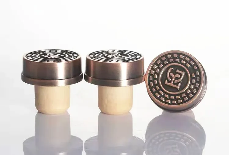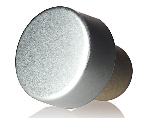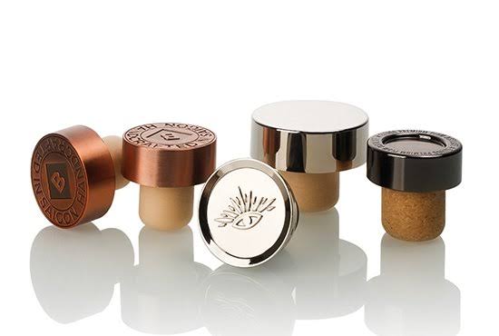
Bottle stopper insertion force testing measures the axial force required to push a bar-top or T-top stopper into its approved seating position. The test helps spirits brands, distilleries, bottlers, private-label buyers, importers, and packaging purchasers determine whether a closure can be applied consistently without damaging the stopper or disrupting production.
A controlled test normally uses a motorized test stand and calibrated load cell to record peak insertion force and the complete force-distance curve. The curve can reveal excessive resistance, bottle-neck interference, misalignment, incomplete seating, or inconsistent stopper compression.
For projects using custom bar-top stoppers for spirits bottles, there is no universal insertion-force limit. The acceptable range must be established for the specific bottle, stopper material, seating depth, and filling process. Final approval should also consider extraction force, leakage, alcohol compatibility, and bottling-line performance.
Bottle Stopper Insertion Force Testing at a Glance
| Test item | Recommended control |
|---|---|
| Test direction | Axial downward compression |
| Main equipment | Motorized test stand with a calibrated load cell |
| Primary outputs | Peak force and complete force-distance curve |
| Controlled variables | Insertion speed, travel, alignment, conditioning, and seating endpoint |
| Post-test inspection | Seating height, stopper tilt, rebound, shaving, and component damage |
| Acceptance limits | Developed for the approved bottle-and-stopper combination |
What Is Bottle Stopper Insertion Force?
Bottle stopper insertion force is the downward force needed to push the functional shank of a closure into the bottle neck until it reaches a defined seating position. It is normally reported in newtons.
Depending on the equipment and test protocol, a report may include:
- Force at initial bottle-mouth contact.
- Maximum force during insertion.
- Force at a specified insertion depth.
- Total insertion travel.
- Force at final seating.
- Variation between samples.
- Stopper rebound after the load is removed.
The complete force-distance curve is usually more informative than a single peak value. It shows how resistance develops throughout the insertion stroke and whether an abnormal force increase occurs at the bottle entrance or deeper inside the neck.
What happens when insertion force is too high?
Excessive insertion force can cause:
- Incomplete seating.
- Tilted stopper heads.
- Shank deformation.
- Surface scraping or shaving.
- Decorative-head damage.
- Increased application-head wear.
- Reduced bottling speed.
- Higher reject rates.
- Bottle-neck damage.
Increasing the pressure of the bottling machine does not necessarily solve the problem. If the cause is an oversized shank, narrow internal bore, incorrect stopper profile, or unsuitable material, additional machine force may increase damage without creating a reliable fit.
What happens when insertion force is too low?
Very low insertion force may indicate:
- An undersized stopper shank.
- An oversized bottle bore.
- Excessive surface treatment or lubrication.
- Insufficient compression recovery.
- Inadequate sealing contact.
These conditions can lead to closure lift, rotation, poor retention, or leakage during storage and transport.
The goal is not to create the tightest possible stopper. It is to achieve a repeatable fit that can be applied efficiently, remain secure during distribution, and provide an acceptable consumer opening experience.
Insertion Force vs. Extraction Force
Insertion and extraction tests evaluate different stages of closure performance.
| Test | Direction | Main purpose |
|---|---|---|
| Insertion force | Stopper is pushed into the bottle | Application, compression, and filling-line compatibility |
| Extraction force | Stopper is pulled from the bottle | Retention and consumer opening effort |
| Opening torque | Stopper is rotated | Twist-and-pull opening behavior |
| Head-to-shank pull test | Decorative top is separated from the insert | Assembly and adhesive strength |
| Leakage test | Closed bottle is stored or conditioned | Seal integrity |
ISO 9727-5 for cylindrical cork stopper extraction-force testing describes a method for determining the force required to remove fully inserted cylindrical cork stoppers. It should not be treated as a universal insertion-force standard for decorative spirits bar tops.
A stopper may be easy to insert but provide insufficient retention after storage. Another may seat consistently but require excessive consumer effort to remove. Insertion force should therefore be reviewed together with extraction, seating, leakage, and production-line data.
For a more detailed discussion of opening resistance, see the bar-top stopper pull-out force and sample-testing guide.
What Affects Bottle Stopper Insertion Force?
1. Bottle-neck geometry and tolerance
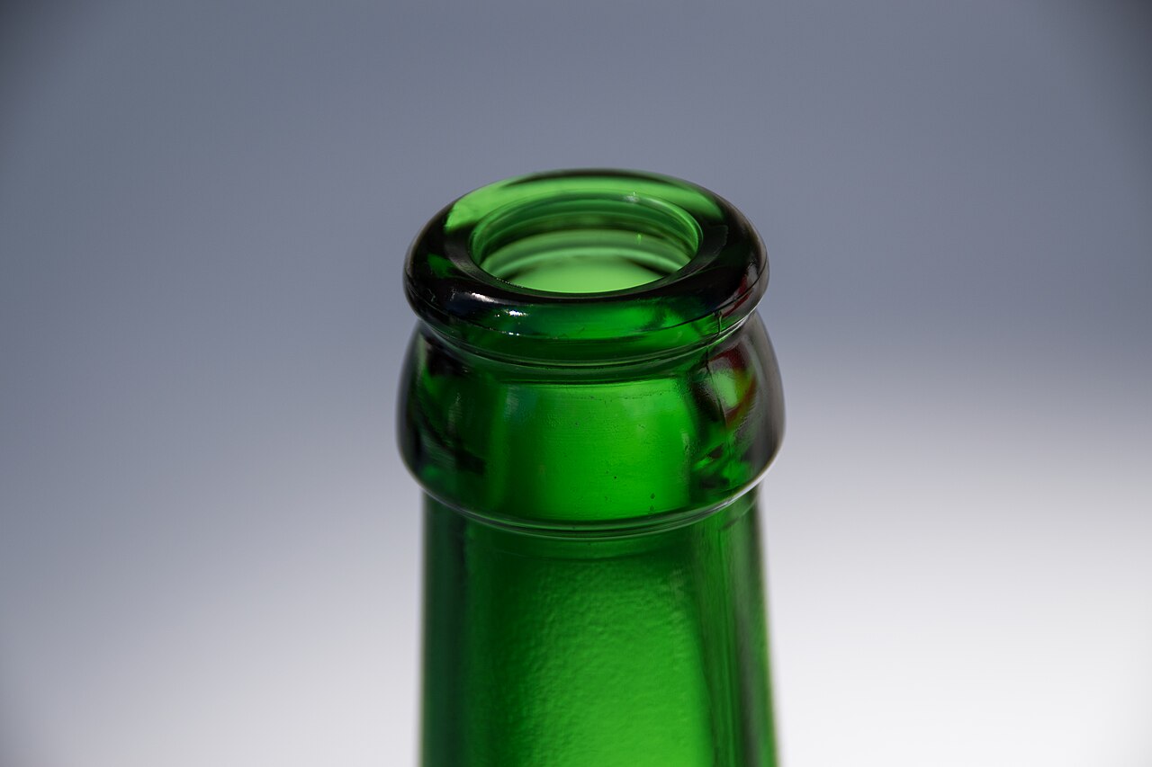
The internal bottle-neck profile is one of the most important variables affecting bottle stopper insertion force testing.
The nominal mouth diameter shown on a bottle drawing does not always describe the complete functional bore. Actual bottles may have:
- Internal taper.
- Ovality.
- Mold-to-mold variation.
- A narrow pinch point.
- A ridge below the opening.
- Different diameters at different depths.
A stopper may enter the bottle mouth easily and then meet excessive resistance farther down the neck.
Measurements should therefore be taken at the depths that correspond to the functional contact area of the stopper shank. Testing should include bottles from relevant molds, production lots, or suppliers.
The spirits bottle-neck fit guide for bar-top stoppers explains why internal bore dimensions, tolerance, insertion depth, and actual bottle samples must be reviewed together.
One bottle cannot represent normal glass-production variation.
2. Stopper shank dimensions and profile
Shank diameter determines the initial interference with the bottle bore, but diameter alone does not define closure fit.
The test result also depends on:
- Functional shank length.
- Taper.
- Rib design.
- Roundness.
- Surface texture.
- Insertion depth.
- Material compressibility.
A tapered shank may produce a gradual rise in force. A straight cylindrical shank may maintain contact over a longer distance. Molded polymer ribs can create several sealing zones while reducing the overall application load.
Simple sizing rules, such as selecting a stopper a fixed amount larger than the bottle opening, may help during preliminary screening. They cannot replace measurements and testing with actual production bottles.
3. Material and compression recovery
Different shank materials respond differently under compression.
| Shank material | Main insertion-force consideration |
|---|---|
| Natural cork | Density, moisture, surface texture, and natural variation |
| Micro-agglomerated cork | Density, dimensional consistency, and coating control |
| Synthetic cork | Polymer hardness, friction, and compression recovery |
| Molded polymer | Resin hardness, rib geometry, and temperature response |
| Hybrid insert | Material-interface stability and long-term performance |
A suitable stopper must compress during insertion and recover sufficiently to maintain contact with the bottle neck.
ISO 9727-4 on dimensional recovery after cork compression demonstrates why recovery should be evaluated rather than judged only by appearance. Its specific method may not apply directly to every decorative T-top closure, but the underlying recovery principle remains relevant during material comparison.
4. Surface treatment and friction
Controlled coatings or lubricants may reduce friction and improve application consistency.
Excessive treatment can also reduce extraction force or retention. A stopper supplier should control:
- Treatment type.
- Application level.
- Curing process.
- Production lot.
- Beverage compatibility.
- Effect on opening performance.
Prototype and production testing should use equivalent surface treatments whenever possible. An untreated prototype may not represent the performance of the final production stopper.
5. Insertion speed and conditioning
Cork-based and polymer materials may respond differently at different compression speeds and temperatures.
Comparative tests should use the same:
- Insertion speed.
- Conditioning period.
- Temperature.
- Seating depth.
- Test direction.
- Data-recording method.
Projects exposed to cold warehouses, warm filling areas, or export containers may require additional conditioned testing. Results obtained under one laboratory environment should not automatically be assumed to represent every storage or bottling condition.
6. Alignment and seating endpoint
The stopper must be centered over the bottle neck, with the force applied along the bottle axis.
Misalignment can produce:
- Artificial force spikes.
- Uneven compression.
- Stopper tilt.
- Shank shaving.
- Decorative-head damage.
- Contact between the fixture and glass.
The test must also define exactly where insertion ends. The endpoint may be:
- A fixed travel distance.
- A specified seating height.
- A target head-to-bottle gap.
- Contact between the stopper head and bottle mouth.
- The position produced by the production applicator.
Without a controlled seating endpoint, test results cannot be compared reliably.
Equipment and Test Controls
A repeatable bottle stopper insertion force test normally requires the following equipment.
| Equipment | Selection criteria |
|---|---|
| Load cell or force gauge | Appropriate range, resolution, current calibration, and overload protection |
| Motorized test stand | Controlled insertion speed and repeatable vertical travel |
| Bottle fixture | Stable vertical alignment without damaging the glass |
| Compression platen | Central loading without damaging the stopper head |
| Test software | Peak force, force-distance curve, and statistical reporting |
The test report should identify the equipment used, load-cell capacity, calibration status, insertion speed, seating endpoint, and data-acquisition method.
The load-cell range should suit the expected force. Equipment with excessive capacity may provide insufficient resolution, while an undersized sensor may overload during an abnormal test.
The bottle fixture must prevent movement without creating damaging point loads on the glass. Custom compression fixtures may be necessary for spherical, sloped, ceramic, glass, or irregular metal stopper heads.
Step-by-Step Bottle Stopper Insertion Force Test Method
Step 1: Define the test objective
State whether the test supports product development, production approval, incoming quality control, filling-line setup, or complaint investigation.
The objective determines the required sample size, component lots, and supporting tests.
Step 2: Identify the bottle and stopper samples
Record:
- Bottle supplier and model.
- Bottle mold or production lot.
- Stopper part number.
- Shank material and dimensions.
- Surface treatment.
- Stopper production lot.
- Previous conditioning or liquid exposure.
Unidentified samples cannot support reliable production decisions or effective root-cause analysis.
Step 3: Inspect and measure the components
Measure the internal bottle bore at the relevant insertion depths.
Measure the stopper shank diameter, functional length, taper, roundness, and profile. Record visible defects such as:
- Chipped or damaged glass.
- Severe neck ovality.
- Molding flash.
- Damaged ribs.
- Contamination.
- Head-to-shank misalignment.
Defective samples should be recorded separately rather than silently removed from the results.
Step 4: Condition the samples
Store all comparison samples under the same defined conditions before testing.
Record:
- Conditioning temperature.
- Conditioning duration.
- Relative humidity when relevant.
- Whether the stopper is new or previously inserted.
- Whether the stopper has contacted the intended spirit.
Consistent conditioning improves comparability between stopper designs and production lots.
Step 5: Set up the equipment
Confirm:
- Load-cell capacity.
- Calibration status.
- Insertion speed.
- Maximum travel.
- Seating endpoint.
- Fixture alignment.
- Data-recording rate.
Zero the sensor before testing. A low-speed setup check can help confirm alignment after changing the bottle or fixture.
Step 6: Insert the stopper
Place the bottle securely in the fixture and center the stopper above the neck.
Start the controlled downward movement and record the complete force-distance curve. Stop at the approved seating position.
Do not continue applying load beyond the endpoint unless the protocol includes a separate overload or structural-strength assessment.
Step 7: Inspect the closed package
After removing the test load, inspect:
- Final seating height.
- Stopper-head alignment.
- Rebound.
- Shank damage.
- Bottle-neck damage.
- Shaving or scraping.
- Visible gaps.
- Head-to-shank movement.
- Decorative-surface damage.
A sample should not pass solely because its peak force is within range. Visual and functional defects must also be considered.
Step 8: Test representative variation
One bottle and one stopper cannot represent normal production variation.
Development screening may begin with 10–30 assemblies for each configuration. Production qualification should include relevant bottle molds, stopper lots, and expected dimensional variation.
The sampling plan should reflect production volume, component variability, previous defect history, and the consequences of leakage or filling-line failure.
Step 9: Report the results
A useful insertion-force report should include:
- Individual force-distance curves.
- Peak insertion force.
- Force at final seating.
- Total insertion travel.
- Average and median.
- Minimum and maximum.
- Standard deviation or coefficient of variation.
- Outlier review.
- Visual observations.
- Bottle and stopper lot numbers.
- Test speed and conditioning.
- Equipment and calibration information.
Averages alone are not sufficient. Two stopper designs may have similar average values but very different variation, seating consistency, or defect rates.
How to Interpret a Force-Distance Curve
The force-distance curve helps identify where resistance develops during insertion.
| Curve pattern | Possible interpretation |
|---|---|
| Smooth progressive rise | Stable alignment and predictable compression |
| High initial spike | Oversized shank, narrow entrance, hard material, or misalignment |
| Secondary spike deeper in the neck | Internal ridge, pinch point, mold variation, or profile interference |
| Very low force | Undersized shank, oversized bore, or excessive lubrication |
| Rising force without full seating | Excessive interference, long shank, neck obstruction, or off-axis loading |
A smooth curve is not automatically a pass. The assembly must still meet seating, extraction, leakage, and appearance requirements.
A secondary force peak can be particularly useful because it may reveal an internal neck restriction that is not visible from the bottle-mouth diameter.
The curve is a diagnostic tool. It should be interpreted together with dimensional measurements and post-test inspection.
How to Establish Insertion-Force QC Limits
Acceptance limits must be developed from the approved bottle, stopper, and application process rather than copied from another spirits packaging project.
A practical qualification process is:
- Compare suitable shank materials, dimensions, and profiles.
- Measure insertion force and final seating height.
- Test immediate and conditioned extraction force.
- Conduct leakage and compatibility testing.
- Run a production-line trial.
- Identify the most stable bottle-and-stopper combination.
- Establish nominal, warning, and rejection limits.
The final quality specification may include:
- Nominal insertion-force target.
- Lower and upper warning limits.
- Lower and upper rejection limits.
- Maximum permitted sample variation.
- Required seating height.
- Stopper-alignment criteria.
- Extraction-force range.
- Leakage requirements.
The lower force limit helps identify loose or insufficiently compressed closures. The upper limit helps identify incomplete seating, application-machine overload, component damage, or excessive consumer opening effort.
Do not approve a stopper simply because it has the lowest insertion force. Approve the configuration that remains within machine capability, seats consistently, passes leakage testing, and provides acceptable conditioned extraction performance.
QC limits should be reviewed whenever there is a change to:
- Bottle supplier.
- Bottle mold.
- Neck specification.
- Stopper material.
- Shank dimensions.
- Surface treatment.
- Filling equipment.
- Application speed.
Related Tests Before Closure Approval
Bottle stopper insertion force testing is only one part of closure qualification.
| Test | Why it is required |
|---|---|
| Extraction force | Confirms retention and consumer opening effort |
| Leakage testing | Confirms seal performance during storage and distribution |
| Alcohol compatibility | Identifies swelling, shrinkage, softening, odor, or coating failure |
| Repeated opening | Evaluates compression recovery and resealing |
| Head-to-shank strength | Confirms adhesive or mechanical assembly integrity |
| Filling-line trial | Verifies application speed, seating consistency, and reject rate |
Testing should reflect realistic use conditions. Depending on the project, this may include upright, tilted, and inverted storage, temperature cycling, vibration, actual-spirit contact, and repeated opening.
Laboratory results should be confirmed on the intended production line because a motorized test stand cannot reproduce every variable of automatic bottling equipment.
Common Problems and Corrective Actions
| Problem | Possible causes | Recommended action |
|---|---|---|
| Excessive insertion force | Large shank, small bore, hard material, or high friction | Reduce interference, revise the profile, or review material and treatment |
| Incomplete seating | Excessive compression, long shank, or internal obstruction | Adjust shank dimensions and inspect the bottle-neck profile |
| Stopper tilt | Poor alignment, uneven stopper head, or bottle variation | Improve guides and verify component geometry |
| Wide force variation | Bottle-mold or stopper-lot variation | Separate results by lot and strengthen dimensional controls |
| Very low insertion force | Small shank, large bore, or excessive lubrication | Increase controlled interference or revise the insert |
| Acceptable force but leakage | Insufficient sealing contact or compatibility failure | Conduct conditioned leakage and retention tests |
| Head separates from shank | Weak adhesive or mechanical joint | Improve assembly design and add bond-strength testing |
| Force changes after storage | Material recovery, temperature, or alcohol exposure | Test aged and conditioned samples |
Corrective action should address the component or process causing the failure rather than only changing the bottling-machine setting.
For example, increasing application pressure may temporarily seat an oversized stopper, but it can also increase component damage, machine wear, and lot-to-lot variation.
How to Qualify a Bottle Stopper Supplier
A capable supplier should evaluate the complete bottle-and-closure system rather than recommend a stopper from one nominal neck diameter.
Ask whether the supplier can:
- Review bottle drawings and physical samples.
- Measure the internal bore at multiple depths.
- Compare different shank materials and profiles.
- Conduct controlled-speed insertion testing.
- Provide complete curves and statistical results.
- Perform extraction, leakage, and compatibility tests.
- Maintain an approved golden sample.
- Provide lot traceability and production specifications.
Kandacork’s bar-top stopper development and fit-testing service supports bottle-neck review, shank matching, sample development, seating evaluation, and pre-production confirmation for spirits packaging projects.
Supplier warning signs
Exercise caution when a supplier:
- Approves fit from photographs only.
- Requests no physical bottle samples.
- Uses only one nominal neck measurement.
- Tests one closure and treats it as representative.
- Reports only that a stopper is “tight” or “loose.”
- Provides no curve, sample quantity, or lot information.
- Starts bulk decoration before technical fit approval.
Recommended approval process
A practical approval process includes five stages:
- Technical review: Confirm the bottle drawing, physical samples, spirit ABV, application method, and line speed.
- Prototype matching: Compare suitable shank materials, dimensions, profiles, and treatments.
- Laboratory validation: Test insertion, extraction, seating, leakage, compatibility, and assembly strength.
- Filling-line trial: Evaluate production-representative application, seating, damage, and reject rates.
- Golden-sample approval: Confirm the final drawing, material, dimensions, force window, seating height, color, decoration, and packaging requirements.
When bottle structure, decoration, closure fit, and export packing must be developed together, buyers can also review complete spirits bottle packaging solutions.
Information required for samples or quotation
To receive a useful recommendation, provide:
- Bottle drawing.
- Physical bottle samples.
- Available neck-bore measurements.
- Spirit type and alcohol percentage.
- Manual or automatic application method.
- Bottling-line speed.
- Preferred shank and stopper-head materials.
- Decoration requirements.
- Estimated order quantity.
- Destination market and target delivery date.
Complete technical information reduces repeated sampling and helps the supplier recommend realistic closure options.
Frequently Asked Questions
What is a good insertion force for a spirits bottle stopper?
There is no universal value.
The correct range must be established for the specific bottle, stopper material, seating depth, and application equipment. It should also pass extraction, leakage, conditioning, and filling-line tests.
Is a tighter stopper always more leak resistant?
No.
Excessive interference can prevent complete seating, deform the shank, damage the package, or make the closure difficult to open. Leakage must be evaluated separately.
Can insertion force be predicted from bottle-neck diameter?
Bottle-neck diameter is an important starting point, but it is not sufficient.
Internal taper, ovality, shank profile, material hardness, surface friction, insertion speed, and seating depth also affect the result.
When should insertion force be retested?
Retesting is recommended after changing the bottle supplier, bottle mold, neck specification, stopper material, shank dimensions, surface treatment, application equipment, or line speed.
The test should also be repeated after leakage, seating, or consumer-opening complaints.